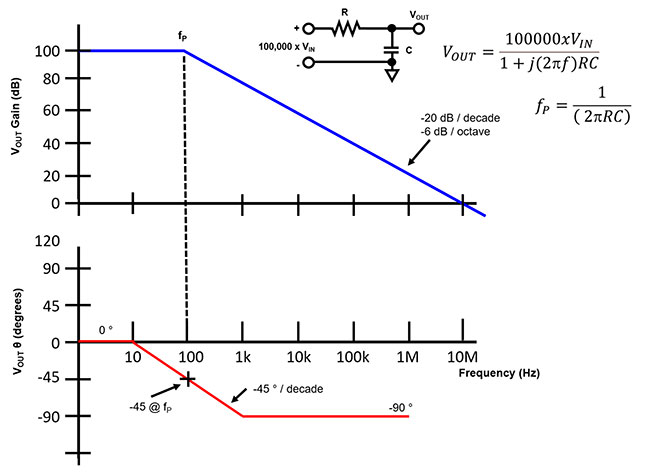
Circuit Diagram Bode Plot
Easy bode plots explained – wira electrical Eis data plotting – pine research instrumentation store Bode plot showing the frequency response of the transfer function g(s
EIS Data Plotting – Pine Research Instrumentation Store
Bode frequency phase diagram magnitude Bode plot diagram template chart circuit angle line pngegg keywords Bode plot example 7
Bode plots
(a) bode plots of the converter with different output voltages withBode plot, gain margin and phase margin (plus diagrams) Ejemplo de diagrama de bodeBode online plots tool draw.
Bode plots pole magnitude explained quadraticTransfer function find bode plot magnitude corresponding below plots following shown solved frequency phase transcribed text show problem been has Magnitude bode plot exampleBode plot of the voltage gain with internal capacitive loading.

Bode plots
Some features of the bode plot of a complex lead compensator. the bodeMatlab script to plot the magnitude and phase of the continuous complex Rl circuit bode diagramBode diagram phase plot rc circuit.
Bode plot exampleBode diagram phase plot rc circuit Solved (a) find the transfer function corresponding to thePlot bode phase matlab error frac sent function 2000 stack.

Is this a matlab bode phase plot error?
Bode compensator damping compensation magnitude gains slopeBode plot Rl circuit bode plotBode converter plots voltages acs.
Bode plots circuit example different eis data networks nyquist figure circuitsBode diagram Circuit diagram bode plotBlank bode plot template web graph paper bode plot;printable template.
Satish kashyap: lecture material on introduction to electrical and
Bode matlab function magnitude gain slope decadeBode diagram rc circuit Online tool to draw bode plotsBode plots (dependence of (a) impedance modulus |z| and (b) phase angle.
How can a bode plot be like that?Bode plot rlc circuit Bode exactBode plot circuit diagram line chart, design, template, angle png.

Bode margin phase electrical4u
Bode plots deal becomesBode plot magnitude Electronic applications: 2.6 the full bode plot: gain and phaseBode plot margin phase gain system stability calculate nyquist comment electrical4u plane half right not diagrams plus transfer.
Stability in feedback amplifiersHow do you graph ω² in a bode plot? Introduction bode circuits electronic electrical applications snapshotsBode plot of frequency response, or magnitude and phase data.

Bode plot, gain margin and phase margin (plus diagrams)
.
.

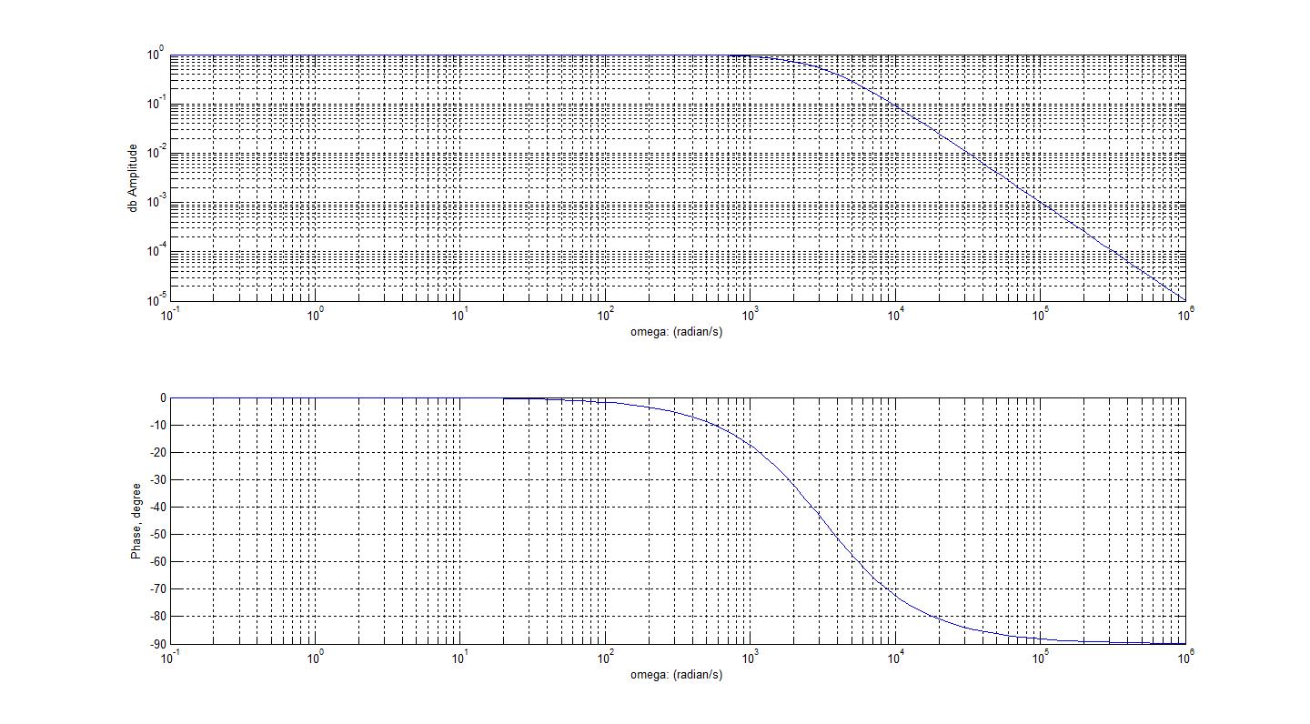
Bode Diagram Rc Circuit

Bode plot Circuit diagram Line chart, design, template, angle png | PNGEgg

Ejemplo De Diagrama De Bode | Diagrama Posterior Ejemplo De MATLAB

Stability in Feedback Amplifiers - Bode and Nyquist Stability

Rl Circuit Bode Diagram

Rl Circuit Bode Plot - Circuit Diagram